 |
LibrePCB Developers Documentation
|
 |
LibrePCB Developers Documentation
|
LibrePCB uses a sophisticated attributes system which makes it possible to display dynamic, context-dependent information in schematics and boards, or to provide additional information for the BOM.
Let's start with a short example. A symbol as defined in the library could look like this:
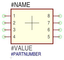
It contains various texts on different layers, and each of them will be replaced by a dynamically determined text while the symbol is part of a schematic:
| Text | Graphics Layer | In schematics substituted by following value |
|---|---|---|
{{NAME}} | sym_names | Designator of the symbol's component in a schematic (e.g. "R5") |
{{VALUE}} | sym_values | Most important attribute of the symbol's component (e.g. "100nF" for a capacitor, or "LM358N" for an OpAmp) Note: With which attribute's value {{VALUE}} is substituted is controlled by the corresponding component, not by the symbol itself. |
{{PARTNUMBER}} | sym_attributes | Part number of the linked device (e.g. "LM358N") Note: Such arbitrary attributes should normally not be added to symbols! Instead, the {{VALUE}} attribute should be used in most cases. |
The {{NAME}} and {{VALUE}} are the most important attributes of a symbol, nearly every symbol will have text items to display them in schematics. They also have their own graphics layer, so it's possible to show or hide the names and values of all symbols in a schematic by changing the visibility of these two layers.
For text items which display other attributes (e.g. {{PARTNUMBER}}, {{RESISTANCE}} or {{FOOBAR}}) the graphics layer sym_attributes should be used. There are no more layers to further distinguish between different attributes.
Exactly the same system also applies to footprints, with the only exception that different graphics layers are used (top_names, bot_names, top_values, ...).
There are two different kinds of attributes:
Built-In Attributes: These attributes are automatically defined by the application and cannot be removed. Some of these attributes values can still be modified by the user, but some are fully defined by the application and are not editable.
User-Defined Attributes: On some scopes (see next chapter), the user can also add arbitrary attributes in addition to the built-in ones. They always have higher priority than the built-in ones, so the user is (theoretically) able to override built-in attributes if necessary.
Attributes can be defined at various objects, with different scopes:
| Object of class | Scope |
|---|---|
| librepcb::project::Project | Whole project (global) |
| librepcb::project::ComponentInstance | One component, its device and symbols |
| librepcb::project::Schematic | One schematic page and its symbols |
| librepcb::project::SI_Symbol | One schematic symbol |
| librepcb::project::Board | One board, its devices and components |
| librepcb::project::BI_Device | One device and its package |
If the value of an attribute needs to be determined for one specific purpose (for example to substitute a text in a symbol), the lookup is done in a specific order. The red arrows of the following diagram show how this order is defined. It also lists all built-in attributes and on which scopes it is possible to add user-defined attributes.
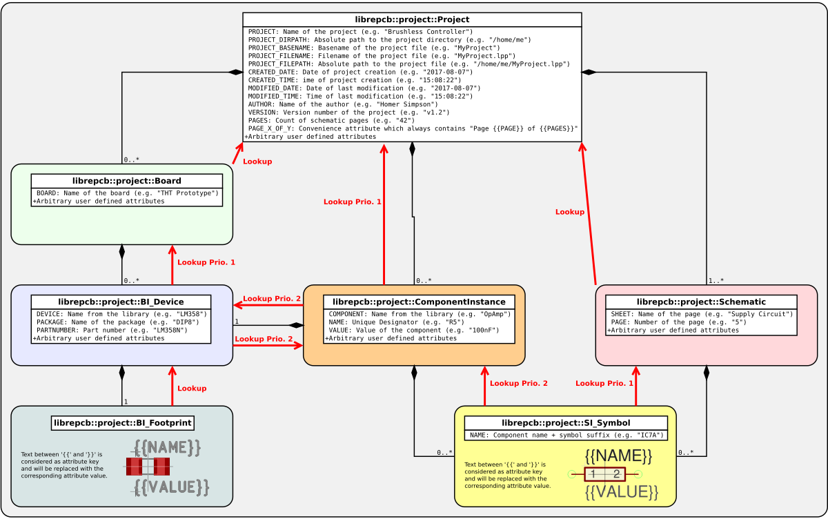
Sometimes the {{VALUE}} text in a symbol or footprint should be substituted by the most exact attribute of a component or device. For example a microcontroller symbol in the schematic should show the exact part number of the corresponding device (Prio. 1). But if no part number is available, the device name should be shown instead (Prio. 2). And if the component does not even have a device assigned, the component name should be shown (Prio. 3). This table shows these three cases for the STM32F103C8T7TR:
| Prio. | Component Name | Device Name | Device Part Number | Desired Substitution of {{VALUE}} |
|---|---|---|---|---|
| 1 | "STM32F103C" | "STM32F103CxT" | "STM32F103C8T7TR" | "STM32F103C8T7TR" |
| 2 | "STM32F103C" | "STM32F103CxT" | N/A | "STM32F103CxT" |
| 3 | "STM32F103C" | N/A | N/A | "STM32F103C" |
To get this "best-match-attribute" behavior, the {{VALUE}} attribute of a component can be set to the value "{{PARTNUMBER or DEVICE or COMPONENT}}". So the 'or' keyword after a key means that a fallback key is following if the first key is not set to a non-empty value. As soon as the first value of the specified keys is not empty, all following keys are ignored.
Of course this system applies to arbitrary attributes, not only to {{VALUE}}.
Attribute keys must only consist of the characters 0-9, a-z, A-Z and '_'. In addition, key names must not start with a digit.
Generally the user wants to select which attributes of a component should be visible in the schematic and in the board. Sometimes schematics and boards should even show different attributes of the same component, for example a capacitor should show the value "100nF/50V" in the schematic, but only "100nF" in the board because of the limited space.
By default, symbols and footprints show all the attributes which are contained in a text item in their library elements (like {{NAME}}, {{VALUE}} and {{PARTNUMBER}} in the symbol above). But in schematics and boards, the user can remove every single of these text items to hide specific attributes. Or to show more attributes, new text items (with arbitrary values) can be added to symbols and footprints. New text items are then added with some default properties (layer, text size, position, ...) which the user needs to adjust afterwards.
Anyway, adding attributes other than {{NAME}} and {{VALUE}} to library symbols and footprints should be used very rarely to keep them as clean and simple as possible. For the most important attributes, the {{VALUE}} text item should be used.
Here are some examples how the attribute system works for standard use-cases:
| Use-Cases | Symbol / Footprint | Component Attributes / Device Attributes | Component Defaults / Device Defaults | Component Values / Device Values | Schematic / Board |
|---|---|---|---|---|---|
| Resistor Capacitor Inductor | 
| {{VALUE}} | "{{RESISTANCE}} {{TOLERANCE}} {{POWER}}" | 
| |
| {{RESISTANCE}} | "10Ω" | ||||
| {{TOLERANCE}} | "1%" | ||||
| {POWER}} | "5W" | ||||

| {{VALUE}} | "{{RESISTANCE}}" | 
| ||
| Diode Transistor OpAmp | 
| {{VALUE}} | "{{ PARTNUMBER or DEVICE }}" | 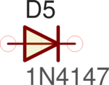
| |

| N/A | 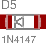
| |||
| LED | 
| {{VALUE}} | "{{ PARTNUMBER or DEVICE }} {{COLOR}}" | 
| |
| {{COLOR}} | |||||

| {{VALUE}} | "{{COLOR}}" | 
| ||
| {{COLOR}} | "RED" | ||||
| Connector | 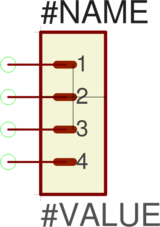
| {{VALUE}} | "{{ PARTNUMBER or DEVICE }}" | 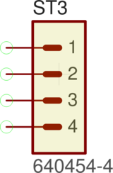
| |

| N/A | 
| |||
| Microcontroller | 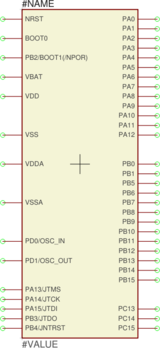
| {{VALUE}} | "{{ PARTNUMBER or DEVICE or COMPONENT }}" | 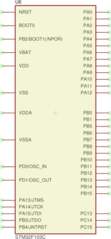
| |
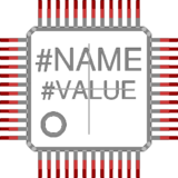
| N/A | 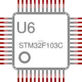
| |||
| Sheet Frame | 
| N/A | 
| ||
The class librepcb::ProjectAttributeLookup allows to query attributes on each of the objects providing any attributes (both built-in and user-defined attributes). However, this class does not perform any text substitution.
The class librepcb::AttributeSubstitutor implements the actual text substitution. From a given input string and an attribute lookup function, the substituted output string is determined and returned.